Isokinetic Sampling Point in Stack Monitoring
Isokinetic Sampling Point in Stack Monitoring – CPCB Guidelines, Traverse Points & Field Insights from Perfect Pollucon Services | Expert in Stack Monitoring with 25+ years of Experience
What is Stack Sampling in Environmental Monitoring?
Stack sampling is a critical part of air quality monitoring and environmental compliance. It involves collecting gas and particulate samples directly from industrial stacks, chimneys, or DG sets to measure pollutants like PM, SO₂, NOx, and CO. The correct selection of stack sampling point ensures the accuracy of emission data and helps comply with CPCB stack monitoring guidelines.
At Perfect Pollucon Services, we have over 25 years of expertise in conducting isokinetic stack sampling as per CPCB and EPA norms. Our team has supported hundreds of industries in avoiding environmental penalties and optimizing their stack monitoring process.
Know about Environmental Quality Monitoring
The sampling point in Stack Monitoring should be far from any disturbance, bends, baffles etc. To select best sampling point it advised that it should be at a distance 5-10 diameters for downstream and 3-5 diameters from upstream disturbance.
Check out this hands-on case study where our team tackled a tough stack emission monitoring challenge and delivered results under pressure.
Know more About Stack monitoring
Where is the Stack Sampling Point?
The stack sampling point should be located away from bends, dampers, fans, or other disturbances to ensure accurate readings. It is recommended to be placed 5-10 diameters downstream and 3-5 diameters upstream from any obstructions.
Size of sampling point
Opening in stack for sampling is absent in majority of stacks. Therefore there has be a provision in stack for sampling points. The size of sampling point can be made in range of 7-10 cm in diameter. Also that extension can be closed during non-sampling period.
Sampling Port Design Specifications
Stack Diameter (mm) | Recommended Sampling Port Size | Cover Type |
---|---|---|
200–500 mm | 7.5 cm | Threaded cap or butterfly valve |
501–900 mm | 10 cm | Flanged blind cover |
>900 mm | 10+ cm | Gasket-sealed blind flange |
What are the Guidelines for Stack Sampling?
The Central Pollution Control Board (CPCB) provides guidelines for stack sampling, including minimum stack height requirements, selection of traverse points, and measurement methods. The sampling should be conducted under isokinetic conditions to ensure representative results.
DG Stack Sampling Point: How It’s Done in Real Sites
Sampling points for DG (Diesel Generator) stack emissions need to be selected carefully since the stack is usually shorter and subject to thermal variation. As per CPCB norms, the DG stack sampling point should be positioned after the exhaust stabilizes — typically 5 diameters downstream and 3 upstream from bends or elbows. Our team ensures correct sampling port location during installation to avoid data skew due to turbulence.
Traverse Points
In order to sample to become representative, it should be collected from various points across the stack. This method is called as Isokinetic Stack Sampling. This is necessary because velocity and concentration of gases will be different across cross section of the stack. So traverse points have to be located to achieve this while selecting Sampling point in Stack monitoring. Generally traverse points are selected from cross section of the stack perpendicular to the gas flow is divided into specified number of equal area.
Number of traverse points may be selected as mentioned in below table:
Cross Section Area of Stack | No. of Traverse Points |
---|---|
0.2 | 4 |
0.2 to 2.5 | 12 |
2.5 and above | 20 |

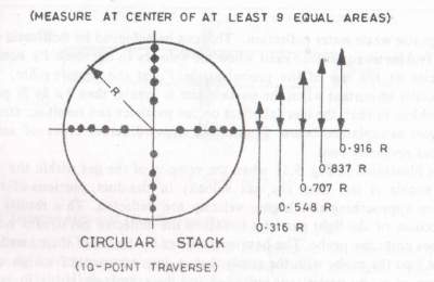
In circular stack, traverse points are located at the centre of equal annular across two perpendicular diameters.

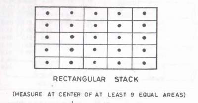
In case of rectangular stacks, the area divided into 12 to 25 equal areas and centres are fixed for each square. The traverse should be carried out at least on nine squares on at least three lines.
Stack Sampling Point Calculation
The correct sampling location is determined using EPA and CPCB guidelines, which specify the number of traverse points based on stack diameter and cross-sectional area. In circular stacks, traverse points are distributed equally along perpendicular diameters, whereas in rectangular stacks, they are divided into 12-25 equal sections.
🔧 Stack Sampling Point Calculator
Read more about Stack Monitoring Procedure
Common Mistakes in Stack Sampling Point Selection
Based on our field experience across 1000+ industrial sites, we’ve observed recurring errors that compromise emission data accuracy. Avoid these to ensure compliance and meaningful results:
- Sampling near bends, fans, or dampers – leads to flow disturbances and non-representative samples.
- Improper port sealing during non-sampling periods – allows leaks or entry of ambient air.
- Insufficient traverse points – gives false confidence in uniformity of emission profiles.
- Incorrect nozzle alignment – impacts isokinetic flow and particle capture accuracy.
PPS’s team ensures that each sampling point is field-verified and aligned with both CPCB and EPA standards before monitoring begins.
Isokinetic Conditions
The efficiency of sampling depends on conditions at which sample was taken. Collected sample should be representative of entire source.
This can be achieved by isokinetic stack sampling. Isokinetic Condition exist when velocity in stack is equal to the velocity at the top of probe nozzle.
This is very important when particle size is greater than 3 µ as because of inertia it can result in wrong sample.
Location of traverse points in Circular Stack (in percentages %)
Diameter (m) | 0.2 | 0.4 | 0.6 | 0.8 | 1 | 1.2 | 1.4 | 1.6 | 1.8 | 2 | 2.2 |
---|---|---|---|---|---|---|---|---|---|---|---|
Inch | 7.9 | 15.7 | 23.6 | 31.5 | 39.4 | 47.2 | 55.1 | 63.0 | 70.9 | 78.7 | 86.6 |
1 | 14.6 | 6.7 | 4.4 | 3.2 | 2.5 | 2.6 | 1.8 | 1.6 | 1.4 | 1.3 | 1.1 |
2 | 85.4 | 25.0 | 14.6 | 10.5 | 8.2 | 6.7 | 5.7 | 4.9 | 4.4 | 3.9 | 3.5 |
3 | 75.0 | 29.6 | 19.4 | 14.6 | 11.8 | 9.9 | 8.5 | 7.5 | 6.7 | 6.0 | 5.5 |
4 | 93.3 | 70.4 | 32.3 | 22.6 | 17.7 | 14.6 | 12.5 | 10.9 | 9.7 | 8.7 | 7.9 |
5 | 85.4 | 67.7 | 34.2 | 25.0 | 20.1 | 16.9 | 14.6 | 12.9 | 11.6 | 10.5 | |
6 | 95.6 | 80.6 | 65.8 | 35.6 | 26.9 | 22.0 | 18.8 | 16.5 | 14.6 | 13.2 | |
7 | 89.5 | 77.4 | 64.4 | 36.6 | 28.3 | 23.6 | 20.4 | 18.0 | 16.1 | ||
8 | 96.8 | 85.4 | 75.0 | 63.4 | 37.5 | 29.6 | 25.0 | 21.8 | 19.4 | ||
9 | 91.8 | 82.3 | 73.1 | 62.5 | 38.2 | 30.6 | 26.2 | 23.0 | |||
10 | 97.4 | 88.2 | 79.9 | 71.7 | 61.8 | 38.8 | 31.5 | 27.2 | |||
11 | 93.3 | 85.4 | 78.0 | 70.4 | 61.2 | 39.3 | 32.3 | ||||
12 | 97.9 | 90.1 | 83.1 | 76.4 | 69.4 | 60.7 | 39.8 | ||||
13 | 94.3 | 87.5 | 81.2 | 75.0 | 68.5 | 60.2 | |||||
14 | 98.2 | 91.5 | 85.4 | 79.6 | 73.8 | 67.7 | |||||
15 | 95.1 | 89.1 | 83.5 | 78.2 | 72.8 | ||||||
16 | 98.4 | 92.5 | 87.1 | 82.0 | 77.0 | ||||||
17 | 95.6 | 90.3 | 85.4 | 80.6 | |||||||
18 | 98.6 | 93.3 | 88.4 | 83.9 | |||||||
19 | 96.1 | 91.3 | 86.8 | ||||||||
20 | 98.7 | 94.0 | 89.5 | ||||||||
21 | 96.5 | 92.1 | |||||||||
22 | 98.9 | 94.5 | |||||||||
23 | 96.8 |
When velocity of the gas in sampling nozzle is less than gas velocity in duct, part of gas stream are deflected. It can be resulted in heavier particles enter into probe resulting non-representative high concentration of heavy particles, hence erroneous weight.
Conversely, Because of deflection if the velocity in probe is higher than that of gas stream is being sampled with excessive amount of lighter particles entering the probe. Hence high concentration of lighter particles and sample weight is on lower side.
It is necessary to select sampling or traverse point in stack monitoring as per calculations and with correct methods, so that errors while collecting sample can be minimized.
💡 Pro Tips from Our Stack Monitoring Engineers
- Use a laser level or cross-hair to align probe with stack diameter when setting up traverse points.
- Never assume uniform flow in short stacks — velocity varies sharply, even with same load.
- Always re-calculate traverse layout when stack size or flow conditions change (like retrofits).
- Train DG operators to maintain exhaust temperatures before testing, especially in winter months.
Learn how to calculate correct stack sampling location using our CPCB-based stack monitoring calculator.
Industry Best Practices Followed by Perfect Pollucon Services
With over two decades of experience in emission testing, PPS follows globally benchmarked practices to ensure high data integrity:
- Dry-run before actual monitoring – to verify accessibility and stable gas flow conditions.
- Use of only Class 1 calibrated instruments – for reliable, court-admissible results.
- Two-tier verification of traverse point layout – by site engineer and QA expert.
- Real-time monitoring validation – our team ensures pressure and velocity graphs are stable before recording data.
- Report QC using 3-point check – engineering, environmental compliance, and legal audit review.
This end-to-end discipline ensures our clients receive zero-noncompliance notices due to sampling errors.
Stack Monitoring Parameters and Limits
Stack monitoring involves measuring key pollutants such as Particulate Matter (PM), Sulfur Dioxide (SO₂), Nitrogen Oxides (NOx), Carbon Monoxide (CO), and Oxygen (O₂). CPCB standards prescribe different limits based on industry type and fuel used.
what are the benefits of stack emission testing?
Let us know your Thoughts or views on this.
Learn More Environmental Monitoring
Read more about Traverse Point in stack monitoring
Explore our stack emission monitoring services for factories, power plants, and DG sets.
Field Highlight: Stack Sampling During Emergency Downtime
At PPS, we often go beyond routine compliance. In one instance, a pharmaceutical client needed urgent stack testing for a DG set during a weekend power failure. Our team mobilized within 3 hours, conducted isokinetic stack sampling at 2:00 AM, and submitted a verified report within 12 hours to prevent production downtime and legal penalties. This kind of responsiveness is what sets PPS apart.
Why Clients Trust Perfect Pollucon Services
“Perfect Pollucon’s on-site team was the only vendor who explained port placement with technical clarity.”
– Anuj Patel, EHS Manager, Pharmaceutical Industry
“We passed our CPCB audit in the first attempt—thanks to PPS’s guidance on stack monitoring.”
– Ramesh Kulkarni, Environment Officer, Textile Manufacturing
“Their team coordinated night-time DG stack sampling flawlessly—no one else offers that kind of reliability.”
– Meenal Shah, Compliance Head, Data Center Facility
It should be located 5–10 diameters downstream and 3–5 diameters upstream from any disturbance like bends or dampers to ensure representative sampling.
Depending on stack diameter and shape, CPCB recommends 12–25 traverse points for circular or rectangular stacks. This ensures velocity and pollutant uniformity across the cross-section.
Isokinetic sampling ensures that the gas enters the probe at the same velocity as the stack flow, preventing over- or under-sampling of particles. This is critical for regulatory compliance and data accuracy.
Rule 5 pertains to emission monitoring protocols, including correct stack height, port location, traverse point setup, and isokinetic sampling method — all of which must comply with CPCB guidelines.
Isokinetic sampling of a stack ensures that the velocity of gas entering the sampling nozzle matches the velocity of the gas stream in the stack, allowing for accurate measurement of particulate pollutants.
It is a method used in stack emission monitoring where the probe collects particles without disturbing their natural trajectory, ensuring a representative sample across varying particle sizes.
Isokinetic conditions are achieved by calibrating the sampling equipment so that the nozzle velocity equals the stack gas velocity, typically using pitot tube measurements and flow balancing.
Isokinetic conditions exist when the gas velocity at the probe nozzle equals the free stream velocity in the stack, minimizing particle loss or overrepresentation due to inertia.
Dear Sir ,
I want to know sampling method of Free Silica in Ambient Air & also test method .